
The new engine rebuild started today, all of my shiny new my parts are set out and ready to go – all of the old parts are lost (even though I bagged everything up, they seem to have disapeared since the tear down 3 months ago). After the false starts with the lost items and further filling the pockets of Just Kampers (did find a my oil pressure valve in a trainer under the stairs) I reach the section on the the Distributor setup -WTF!!!! Although I know my way around DC Electrics, the set up of this component baffled me completely. Although the reasons are various I have summarised a couple below:
- Every guide and manual I have read do not include the Type 4 engine (I have bought 4 to day!) and certainly not the CJ! This seems to be a common issue for technical issues relating to this engine, especially for a first timer like me. If you get one of these engines prepare yourself for this!
- When I found a couple of decent looking articles they completely contradicted themselves! Again seems common amongst a lot of install work!
- After a little research on the engine I discovered it was a fuel injected engine with no fuel injection. This alters the the type of distributor that should be used, no idea if this is true or whether there is a completely good reason for the non-fuel injection.
- All of the set-up guides I read mention two separate set-ups, one for a centrifugal and one for a vacuum dizzy (had no idea what this meant at the time!). The dizzy on the van was supposed to be set-up as a vacuum but this was blocked up with a nut. We’ll come onto that later when I figure the whole thing out and stop spouting a load of old bull!
- I’m an Idiot!
So let’s begin by unravelling the enigma of these little fellas!
NOTE: This is my interpretation of the workings of this component (as with all of these blogs I am more than open to correction from folk far more experienced than myself, so, pretty much everyone else!)
So, firstly, what is the relationship between the dizzy and its ‘points’ in relation to the actual mechanical components within the engine itself?
NOTE: I highly advise reading the Engine Fundamentals book produced by Hilliers for a detailed description of this relationship, a great book every budding mechanic needs to read this before picking up a spanner.
Anyway, here goes:
- Your air-cooled engine has 4 cylinders which contain 4 pistons.
- Each cylinder has 4 strokes – Compression, Combustion, Power and Exhaust.
- In order for a piston to engage it is compressed in the cylinder forming extremely high pressure, this ensures that the flammable liquid that is inserted into it lights and explodes in a controlled environment very easily (compressed air gets very hot!).
- Now in order for this to happen you need a spark, and this spark needs to engage at a precise moment in time – at the very top of the compression cycle. This is referred to as TDC or Top Dead Centre – now each piston has a TDC, however, to control the timing of the engine we are only interested in Piston 1’s TDC. TAKE NOTE THIS IS A VERY IMPORTANT REFERENCE/INDEX POINT. In reality we are actually interested in a combustion point somewhat earlier (again very precise!) at a period called BTDC or Before Top Dead Centre. We will come onto what this means when we actually set up the timing of the engine.
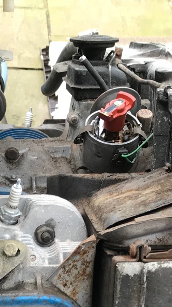
- Now, in order for that to happen you need to time this very accurately. This is ensured by the connection of the Distribution Drive Shaft into the Crank Shaft (which in term is connect to the Camshaft, which connect the valves that control the ingress and egress of cylinder gases via the Pushrods). The Distribution Drive Shaft is in turn connected to the rotor of the Distributor (see picture), which, in turn is connects the Coil (this produces 20,000v) to the spark plugs via the Distributor Cap (check inside and you should find a carbon brush) and the HT (high tension) leads.
Once you understand this relationship you are getting onto a winner! The next thing is to ensure that certain PHYSICAL index points on your engine correlate. Again, you can just mark up your existing distributor and replace with no worries (apparently). I WANT TO EMPHASISE NOTHING ON MY VAN WORKED, EVERYTHING I CAME ACROSS WAS A SHODDY REPAIR, SO I WANTED TO START FROM SCRATCH, LEARN A FEW THINGS IN THE PROCESS!
- So let’s start with the first step in my reassembly of this component. I am at a point where my crank case is in 2 halves, I have installed the Crank and the Cam and aligned the index points (see photo).

- At this point finding TDC is very easy – you grab Piston 1 and pull it to its highest point (I know – doesn’t sound too scientific, however, if you don’t do this at this point you will end up putting a screwie through a spark plug recess to find it at some point! A lot easier when you can see the actual piston IMO) – this is TDC. During the next phases continually check you haven’t moved the Crank.
- The next piece of the jigsaw is to install your Distributor Driveshaft. The first thing to note is that on the Type 4 it has a large Shim with oil grooves in it that needs to be attached. I DID NOT HAVE ONE! YOU CANNOT SOURCE THEM ANYWHERE! So, I ended up buying a second hand Drive Shaft off eBay just for the Shim – quick £40!!!! You attach the Shim to the Shaft with a healthy blob of heavy grease. This is not for lubrication but so the Shim does not fall off the shaft and drop into the engine case below the Crank (you will have to remove the Cam and Crank it this happens – a right Buggers Muddle)! On a Late Bay or Type 4 the keyway on the Drive Shaft needs to be inserted at a preset orientation – this is a 12 degree offset to the centre Crank Case line (something that my manual recommended we do – ref Bentley go to page 14). I could not make head nor tails of this so just guessed what looked OK. Next slot onto the Distributor itself and insert into the case post a good heavy oiling.
- You will notice a notch (I also painted a blob on this part of the dizzy) on the rim of the Distributor – this is your No.1 firing point. Ensuring that the rotor does not move and gently rotate the housing of the Distributor until that notch marries up with the point of the rotor itself. You will know which end of the rotor is the point as it has the brass/copper connection on the top!
- Now gently move the clamp and connect to the associated stud on the engine case. Done!!!!!!
- As a bonus you now know it is in correctly marked up for next time!!!!!
So, in theory now we have completed this we should be able to start the engine and calibrate the timing. For me, however, this was not possible as my engine was still in 2 parts. BUMMER! I will however include a video once the engine is complete on how all of this worked out for – a live Death or Glory moment!
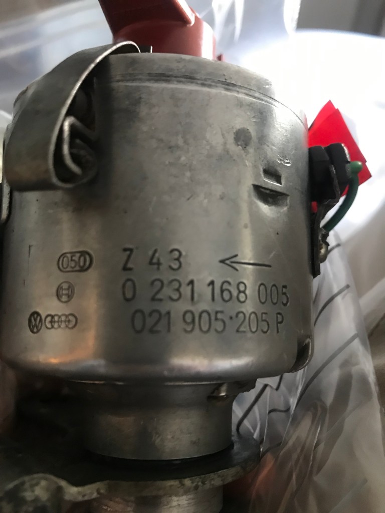
For those of you that haven’t slipped into a coma yet I have dropped a pic of the Distributor Serial Number below. Something important to note here, when you actually calibrate the timing you will need some key figures to set up correctly. These are the Ignition Advance at Idle (900 RPM) and the Ignition Advance under Load or High Revs (3500 RPM). I lifted these straight out of the Bentley manual. I have inserted them below the pictures.
So, first start of the van today. Wired her up and turned her over, starter motor kicks in and engine not firing up. All the work, the blood, sweat and tears of the last 10 months and nothing. There goes the night of glory I had planned. So what next, the moment I had dreaded – trouble shooting. So having read a little I started with the basic elements needed to get her going:
- Fuel.
- Air.
- Spark.
So, having spent a good day going over the wiring my Type 4 is wired as per the 1976 Bentley diagram with the exception of the diagnostic unit. I am guessing by the fact it had been ripped out it was more trouble than not but happy to be corrected on this. The only slight difference I have is that my fuel pump is an electric in-line pump and was connected direct to terminal 15 on the coil (positive +) – probably a little unsafe, relay ordered. I had replaced the fuel lines and filters and connected them to the carb, so barring carb issues I was happy here. So when key engaged, fuel pump ticks and fuel being pumped out – also happy I have 12V on the coil at turn over, 12V to the pump and more importantly fuel to the carb. Checkpoint 1 – SORTED! Unless Carb shagged???
Next Air, now I know there are no blockages and air filter is new. Easy! Checkpoint 2 – SORTED!
So now the complicated piece – Spark! First things first, is everything connected up as it should be? YES. So, let’s undo a plug and work back. Plug one unscrewed (easiest one to get to with tinware on!) Next earth the cathode to the engine block and turn over. NO SPARK! Now, my HT leads are all new, but the distributor is not, let’s earth the lead going to the central position on the distributor cap and turn over – STILL NO SPARK (this does not discount a faulty distributor cap, it means there is a problem earlier in the circuit somewhere). So, worked back to the condenser or coil – 12V on terminal 15 – CHECK! Continuity (the green lead) between Terminal 1 and the points – CHECK! So, now chin scratching time. Time to check the relationship between the points and TDC on Cylinder 1. Now when I built the engine the TDC mark was all marked on the distributor (and checked several times during the rebuild) so I know my mark is right. At this point in the engine cycle you should have the points open – mine are which is good, right?? So in theory this should induce the 20,000 Volts needed to generate a spark, but it isn’t ??? SHIT BALLS! So this could be one of two things (my opinion as Vehicle Electrician with 9 minutes experience!). The coil is buggered -1. The points are buggered – 2. Cheapest thing to test is the gap clearance in the points – this should be xxxxx. If this is correct the only other component to worry about is the capacitor – if you think this is buggered just buy some new points – they cost £3!!! All of this is OK! Next thing is our only other option – buy a new coil, these are not £3 but £65. Ordered and now retesting..
Thought it might be useful to add a little science section on the how a spark is actually generated, clever lads them old fella’s! Hopefully helps with the fault finding process:
So a condenser or coil is essentially a huge inductor. Imagine two coils wrapped around each other and in turn a magnet. One coil is fed by 12V and has a small amount of coils. 12V flows through this to earth via the points until they open. When they open , this causes a reverse voltage, which in turn creates an Electro Magnetic Field (EMF) which in turn creates a huge voltage in the secondary coil, which has a huge amount of coils (in our case and conveniently 20,000 volts) which is fed in turn to the spark plugs via the distributor cap – SIMPLES!!!
