
So, the electrics in my van are buggered. It is evident that there have been a lot of PO’s playing behind my dashboard and they have really screwed it up. I have a long list of repairs that are needed before I feel the van is ready to drive and in this post I am going to tackle the the fuel gauge. In theory this should be simple – there are not really that many parts to it, but, as in all things Camper nothing ever is!
So the principal components in the circuit are as follows:
- The gauge!
- Voltage stabiliser
- Fuel Sender/Feeder
- Power/Earth
So the current state of affairs with the fuel circuit is that the gauge is at permanent zero. There is no movement in the needle at all, quite honestly this could be anything at this stage. No bother guessing!!!
Testing the circuit is extremely simple once you understand its operation and what the component parts do. So let’s discuss this first before I explain the testing and repair of my circuit.
- In the fuel tank is the sender unit. This is nothing fancy, basically it consists of a float attached to a variable resistor via an arm – almost identical to the one you would find in a water tank. The operation of this is simple, as the arm moves upwards reflecting an increase in fuel level the resistance of the variable resistor decreases. The opposite is true when the fuel reduces. There are two connectors on the unit, one that is connected to the voltage source and the other that should be connect to a known good earth in the vehicle. The total resistance of the sender at max should be in the magnitude of 70 ohms.
- The voltage stabiliser is a device that, as it suggests, stabilises the voltage being fed to the other parts of the circuit. Why is this important? Well, when the vehicle runs the voltage across the battery varies, it will increase when the alternator kicks in and decrease any time you turn anything on (stereo, lights, indicators etc.). This would result in the gauge continually changing – not good! The stabiliser therefor provides a steady state voltage to the circuit irrelevant of the input voltage. There are 3 connectors that need to be accounted for here. Input voltage, Output voltage that connects to the gauge and earth. Be aware that the Output Voltage is not a steady 12 Volts but should be roughly half of this.
- The gauge is an extremely simple affair and is nothing more than an analogue voltage meter. This has two connectors, one is the Input Voltage that connects to the Voltage Stabiliser and the other is the Output Voltage that connects to the Fuel Sender. There is no connection to earth on this device.
So, let’s start a few basic tests. This should be approached logically, be aware that, you, just like me may have several problems which can make findings confusing. My advice, isolate individual components and change/repair if broken before moving onto the next section.
- Fuel Sender test in the following sequence:
- Cables are connected and they are the right way around. Positive goes to the post on the inner section of the Sender, Earth to the outside. In my case 1977-8 Bus the Positive cable is Brown, however, so is the Earth!!!
- Check continuity between Earth and Chassis. Use the diode setting on your digital multimeter and you should get a beep if connected. Mine was.
- Check for a positive voltage on the Positive Lead (disconnect) before checking. You should have a reading of around 5-6 volts. I did not!
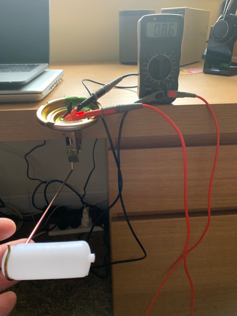
- Next check the resistance of the Sender. Now, no matter the volume of fuel in the tank you should have anywhere in the region of 7 ohms to 70 ohms. I have an open circuit here indicating that the resistor in the Sender was faulty. Having purchased a new one from JK I can confirm the resistance that you would expect as per photos below. This is a very easy to test to conduct, set your multimeter to ohm, attach the positive lead to positive on the sender and the negative lead to chassis. As an aside the Sender Unit is extremely difficult to access with the engine in place. You firstly have to remove the firewall, and then you can just about feel it with your fingers. The previous owner of my van had actually cut an access hatch from above which made life a lot easier! So FAULT 1 FOUND & FIXED.

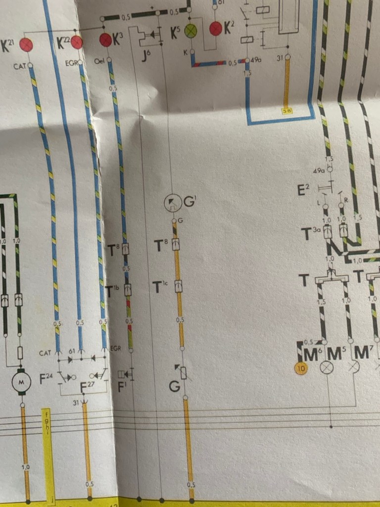
2. So the next thing to check is the continuity of the wire through the loom to the dashboard. This is easiest done with a cable tester. This device simply sends a signal through a cable that is traced by picking up a tone at the other end. No tone – no continuity. It also ensure that you have the correct cable connected. So, from the Sender you should have a brown cable going to a spade connector. This then is connect to another Brown cable through the main loom into the large 8-Way connector in the dashboard (mine is next to the fuse box). From here you should have brown and black connector going to the output of the gauge. Connectivity for me was there, however it was connected to the Stabiliser which was incorrect. Once this was connected – still no reading on the gauge so more to do!!!
3. Fuel Gauge: There is little to test here other than correct connectivity. Be aware there should be no connection to earth here! Mine was connected to earth due to the fact the plastic isolating bracket on the back of the gauge was installed incorrectly. Test this vigilantly! FAULT 2 corrected! Now ensure that the little Red jumper lead is connected to the Output of the Voltage Stabiliser and that you have a reading here of 5-6 Volts. I have nothing!!!
4. Voltage Stabiliser: Test this device in the following sequence.
- At the input to the device you should have around 12.5 Volts. In my case I had 12.76 volts. This is the battery voltage.
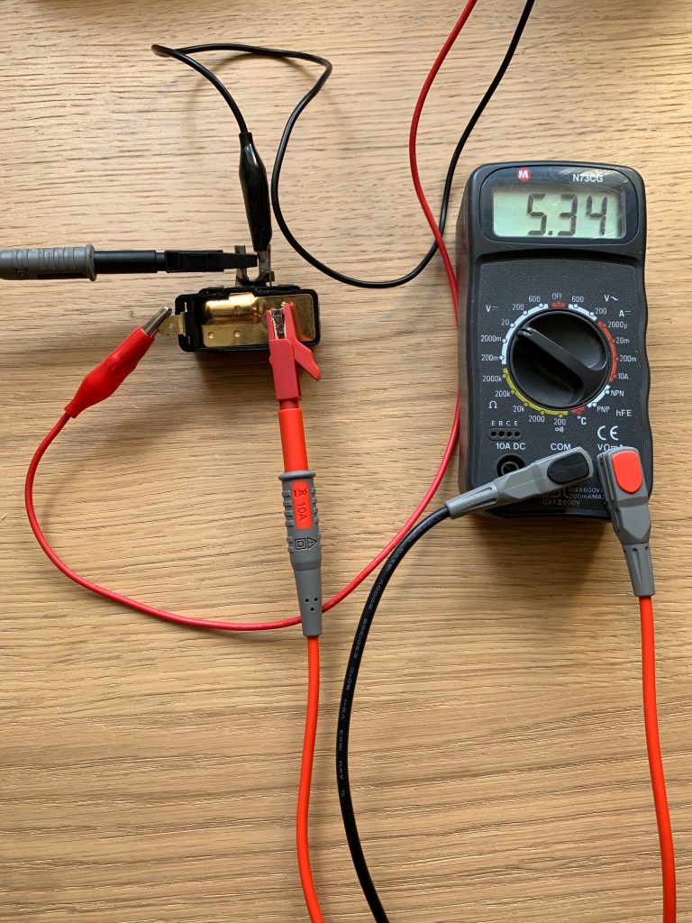
- On the Output of the device you should have around 5-6 Volts continuously. I had a really erratic reading here, literally all over the place. In the end I placed an analogue meter on this and the needle was going back and forth between 0-7 Volts. This unit was certainly faulty. Another one ordered from JK and tested on the bench and a consistent 5.3 Volts – as per photo below.
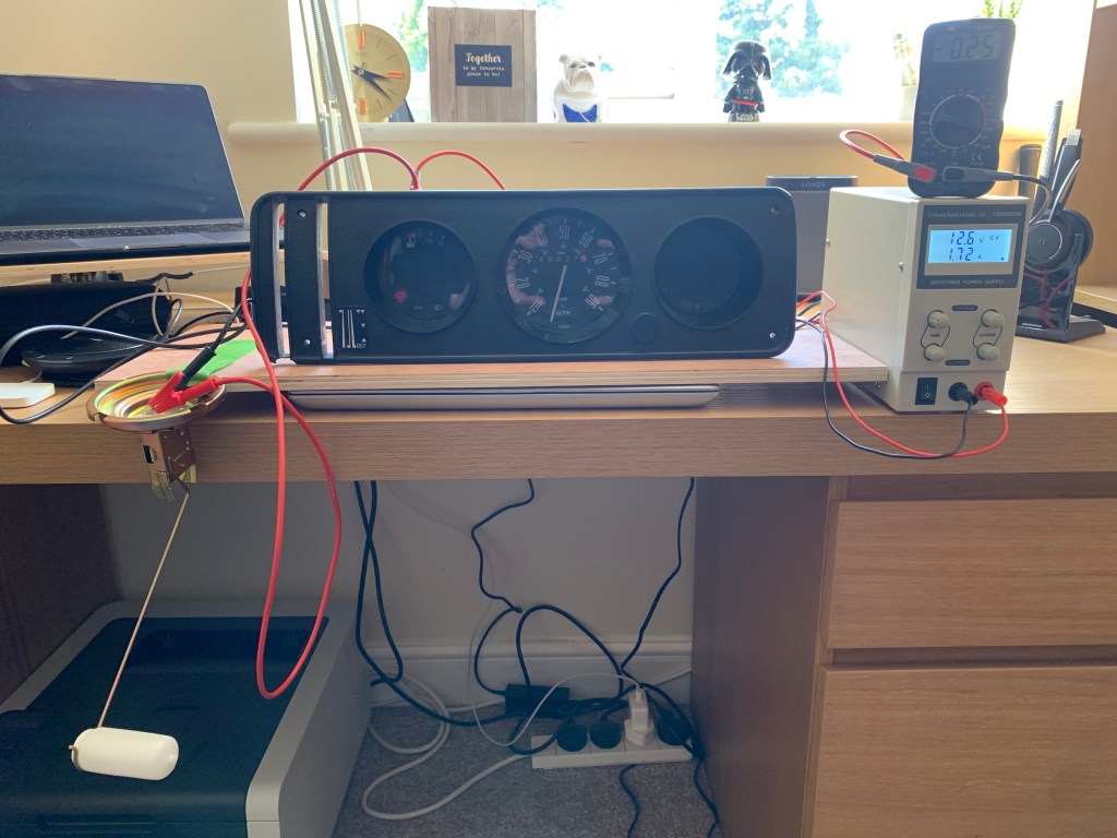
5. Complete Test: Now that all is working in theory everything should work and we should see our fuel gauge move. For ease I have taken out the dashboard instruments and connected them on the bench with a few readings so you can corroborate in your van. SIMPLES!!!

HOPE THIS WAS USEFUL – TIME TAKEN TO GET THIS SORTED AND WORKING INN THE VAN WAS ABOUT 5-6 HOURS.
