
The list of electrical faults on the van has been long. Having now fixed the majority we come to our latest little treat – the headlight dimmer relay and associated switch.
PROBLEM: Pull switch to first position and you get sidelights (with either engine on off or on). Pull the switch to the second position and you still have sidelights, when at this point you should have dipped beam. If you engage the Main Beam via the stalk (to avoid confusion – this is the only way you can engage Main Beam – I was confused!) you get nothing with the engine off and nothing with the engine running.
OK – so before we start it is vital to understand the main components of this circuit and how you engage the separate lights and what to expect. There is nothing unique about the VW Headlight Circuit it has 5 main components:
- 12V DC, of which there are 3 separate feeds (we will come onto this later).
- Earth, of which there are 3 separate connection types, one via the Main Beam Stalk, one via the headlights and one via the instrument panel.
- Dashboard Switch – there should be five poles (or contacts) that feed 3 separate circuits, Park & Side Lights, Dash Bulbs and the Dimmer Relay.
- Dimmer Relay, of which consists of 2 poles, one that feeds the Main Beam and one that feeds Dipped Beam.
- Lights – of which there are 5 types, Park & Side, Main Beam, Dipped Beam, Dashboard Illumination Bulbs (x2) and the Dashboard Main Beam Indicator Bulb (looks Blue when illuminated via dashboard lense)
Before we talk through how to engage the lights it may be worth going through the UK naming convention to avoid confusion (I am from UK). Most of the guides and articles that I have read have been written by our American cousins and can cause a little confusion! I am only going to cover this in the context of headlights..
- Side & Park Lights – on my van this is a dimmed headlight, this was regulatory on German roads hence its installation. It is not a regulatory law on UK highways. It was typically used to illuminate the vehicle to other drivers if parked on the side of the road – usually the only lights illuminated would be those closest to the middle of the road.
- Dipped Beam – this is the headlight mode that a driver would use 90% of the time when driving at night, as it allows vision in the dark without dazzling oncoming traffic.
- Main Beam – this is engaged when you need to see further out and is the mode that blinds other drivers if not disengaged. It is also commonly used to ‘flash’ other drivers to indicate to to them.
Now that’s covered, lets go through how we engage the separate light circuits, this sounds basic, however caused me some confusion when I started fault finding this circuit.
- To engage Side & Park pull out the Switch to the Number 1 position. This can be engaged with Ignition On/Off.
- To engage Dipped Beam pull out the Switch to the Number 2 position. This can only be engaged with Ignition On. My initial understanding that Main Beam was engaged here and Dipped Beam was the Number 1 position – I WAS WRONG!
- Main Beam can be engaged in 2 separate ways, however it can ONLY be operated by use of the Main Beam Stalk on the Steering Column. If pulled when the Switch is in any other mode other than the Number 2 position you will get Main Beam for the duration of the ‘Pull’. If you require permanent Main Beam then you need to engage the Switch in the Number 2 position and pull the Main Beam Stalk. This will now engage Main Beam. to disengage simply pull the Main Beam Stalk again.
So, now lets cover the electrical operation of the circuit and how it should all be connected up in the van. As per the previous paragraph I am aware of an anomaly between the USA vans and the Euro vans. They seem to have different Dimmer Relays. The van I have is a Cali import, however has the Euro spec 5 pole relay this is in contradiction to the VW wiring diagrams and the USA buses which have 4 pole relays. We will come onto how these work a little later. Below is a complete wiring diagram of the Headlamp circuit, followed by a description. You should be able to loosely correlate this to your year’s wiring diagram provided in the Bentley manuals.
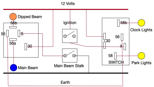
SO THE POINT TO NOTE HERE IS THAT TERMINAL 30 ON THE RELAY IS CONNECTED TO 12V. THE CIRCUIT DOES NOT WORK IF NOT. I CONNECTED THIS TO 12V VIA THE FUSE BOX. THIS IS NOT ON THE WIRING DIAGRAM. HOPEFULLY THIS SAVES YOU A TONNE OF TIME WHEN TROUBLESHOOTING THIS – TOOK ME A GOOD WHILE TO FIGURE THIS ONE OUT!


Now, let’s look at what to expect on the terminals at different stages of switch engagement. I will also call out the faults I found and what I did to rectify the faults.
- At the switch you can see from the diagram that there are 5 different terminals. In no particular order these are:
- 30 – This is connected to 12V via the fuse box. You should always have 12Volts here. Test with your Multimeter on DC V setting and you should roughly have the same Voltage as you see at the battery. On my circuit I did – good start.
- 58a – Once you pull out the switch – you should have 12V here. This can easily be identified by the lights being on. However, always good to double check with the Multimeter again. I had 12V here.
- X – you will only get 12V here once you turn the ignition on. You will see more than 12V (around 14V when the engine is running)
- 58b – You should see 12V here when ignition on or off. This is the 12Volt supply that powers the instrument back light bulbs. It only engages once you pull the switch. Also, as was the case for me your bulbs should light.
- 56 – You should have 12V here once the ignition is on and the switch is pulled. This is the 12V signal voltage that engages the relay. Do not confuse this with a direct voltage that can supply the headlights, this will melt the switch hence the need of the relay in the first place.
- So, the main fault I had was that under no circumstances would Flash or Main Beam would engage. The fault here is easily determined:
- Audio check – Do you hear a discernible ‘click’ when the stalk is pulled? This is the sound of the relay engaging. If not go to Point 2. If yes you probably have a wiring or bulb problem from the relay to the lights. Also check for bad earthing.
- When you pull on the stalk check the connectivity at the stalk itself. You should only have connectivity on temporary pull. If permanent or not at all. Your stalk is buggered, get onto the fellas at JK! If all good goto point 3.
- Check you have 12V at terminal 30. If not start to trace back and find connectivity issue. If all good then goto point 4.
- Check for 12V at terminal 56a (remember that you will both energise and de-energise the relay with the stalk). I incidentally had 0V here no matter what! Here is my fault, now next step is to ascertain is it the relay or the earth. Terminal S is earthed so relay buggered! Again get onto JK.
So, all the wiring double check in ‘situ’ in the van and we now have good main beam. Total time taken to get there including the research about 2-3 hours. Hope this is useful…
